|
Getting your Trinity Audio player ready...
|
Lensometer
Lensometer is an instrument used to measure the spherical, cylindrical power, and axis of an optical prescription to locate the optical center or measure the reference point and determine the base, direction, and amount of prism present.
It is a device to measure refractive power prescription of unknown lenses.
Lensometer is also known as foci meter, verto meter, refraction meter, vertex foci meter, and lensmeter depending upon the manufacturer.
Who Invented the Lensometer?
Antoine Claudet designed the photographometer in 1848. This device was used for measuring the intensity of photogenic rays.
In the following year, he designed the foci meter used to find the correct focus in photographic portraiture.
Hermann Snellen developed an instrument known as the Phakometer in 1876.
This instrument has a setup similar to the optical bench and was used to measure the power and location of the optical center of a convex lens.
It was in 1912 that Troppman proposed the idea of a direct measuring instrument.
A patent was filed in 1921 by Edgar Derry Tillyer from the American Optical Company proposing the first lensometer.
This design projected the measurements of the target on a screen in order to eliminate the requirement for correction of the refractive error of the observer and to reduce the need of peering down a telescope into the device. (www.lambdageeks.com)
There are two types of lensometers.
- Manual lensometer
- Automated lensometer
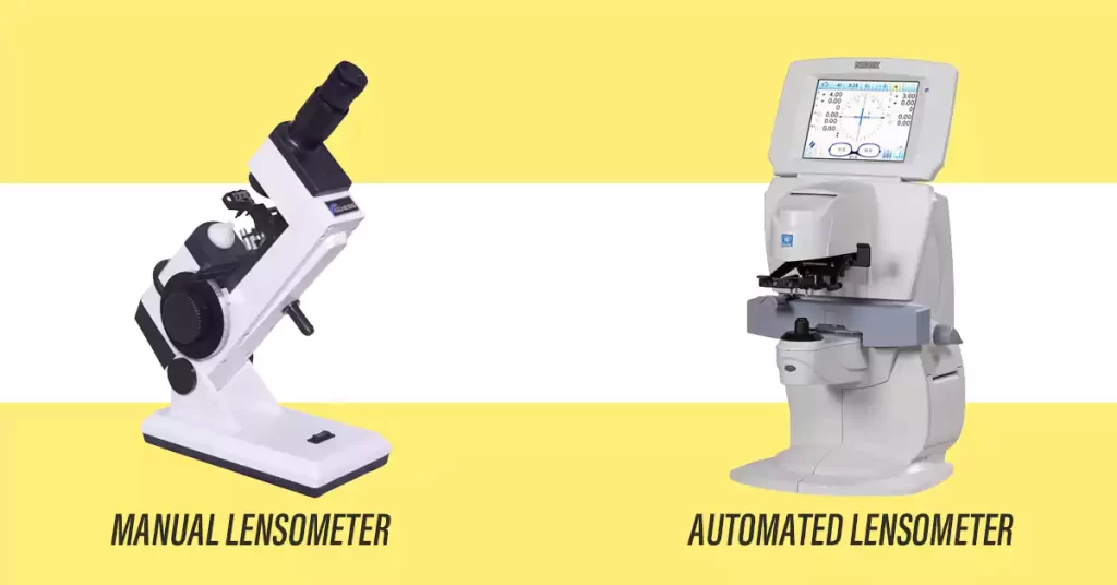
Manual Lensometer: Manual Lensometer can be defined as an instrument used by an optometrist to find the back-vertex or the front vertex power of the eyeglasses. A manual lensometer is portable and can be carried anywhere. But a person needs to have a better idea to measure the power of a lens.
Automated Lensometer: It is a fully automatic well-programmed device primarily used in clinics. It is easy and faster and can print prescriptions. It is less accurate when compared to a manual lensometer.
Principle of Lensometer.
Badal Principal: The Badal principle is based on the observation that if the eye is placed at the focal point of a positive lens, the virtual image of an object located between the lens and anterior focal point will always subtend the same visual angle.
Badal optics are disclosed in which aperture array at an optical system under test is interrogated for the deflection of light between a detector array conjugate with the aperture array of the optical system under test being examined.
The excursion is measured in a plane normal to the axis of the Badal optics instead of observing towards and away from image focus along the axis of the Badal system.
In the case of an objective refractor, the eye is illuminated at the retina with a test spot, preferably light in the infrared.
An image of the detector array is relayed by a relay lens through the Badal optics to the cornea of the eye, the lens under test.
The light emanating from the test spot on the retina passes through the eye lens at the image of the detector array.
This light undergoes excursion in accordance with the power of the eye lens under test at each aperture of the detector array.
The extent of this excursion is determined by a moving boundary locus between the image of the detector array itself.
This excursion is related directly to the eye prescription.
Parts of Manual Lensmeter:
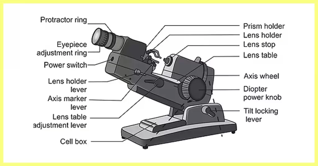
- Eyepiece: It is that part of the lensometer through which the viewer can view the internal components of the lensmeter.
- Prism axis scale: The prism axis scale helps in the orientation of the prism axis.
- Power wheel: It is used to clear the filter and find out the spherical and cylindrical power of the given lens.
- Cylindrical axis wheel: It rotates the target to find the cylindrical axis.
- Lens holder: It is used to hold the lens in its proper position.
- Prism diopter power scale: Displays prism amount.
- ON-OFF Switch: Power switch.
- Prism compensative device knob: It helps in reading prism amounts that are greater than five prism diopters.
- Spectacle table: It provides a resting place for the spectacle frame while neutralizing the power of the lens.
- Spectacle table lever: It helps raise or lower the level of the spectacle table according to the user.
- Locking lever: the locking lever helps elevate and depress the instrument’s position according to the users.
- Filter lever: The filter lever can incorporate or remove the green filter.
- Lamk access cover: it is used for changing/altering the manual lensometer bulb.
- Lens marker: The handle control’s the pins and is used to mark the optical center or the prism reference points.
Uses of lensometer.
The function of the lensometer is to determine the characteristics of a lens, including:
- Power
- Optical center location
- Measure reference point location
- Prism power/direction
- Cylindrical axis orientation
The lensometer is also used to place marks on a lens to ensure the proper placement of the lens during the fabrication process.
Manual Lensometer: Related Terminology
- Mires: Lines, thick and thin, used as measurement images.
- Sphere: It is a lens with similar power in all meridians. It is used to correct simple refractive errors (myopia or hyperopia, also presbyopia) and is measured in diopter.
- Cylinder: It is a lens with different refractive power in different meridians. It is used to correct astigmatism, and it is measured in diopter.
- Axis: Meridian of cylinder lens with the minimum refractive power. It is perpendicular to the meridian with maximum power, and it is expressed in degrees.
- Prism: A transparent, wedge-shaped material with two flat surfaces inclined at a given angle that connects to a point called the apex. Two connected surfaces are resting on the base of the prism. Prisms are used to help the eye to work together by bending or refracting light.
How to perform Lensometry:
Procedure for Single Vision Lenses

- Set the power wheel to zero
- Set the prism compensator to zero
- Focus the eyepiece. Rotate the eyepiece counterclockwise until the reticle is blurred. Turn the eyepiece clockwise until the reticle is just clear (so as not to over minus the reticle)
- Check the power calibration. Turn the power wheel into the plus and slowly decrease the power until the lensometer target just sharply focuses (DO NOT oscillate the wheel back and forth to find the best focus). The power wheel should read zero if the instrument is in proper calibration.
- If the power wheel does not read zero, refocus the eyepiece and recheck the calibration. If the power wheel still does not read zero, the error must be compensated for on all future measurements made with the lensometer.
- Measure the lens back vertex power in minus cylinder form – Always start with the right lens!
- Starting with the right lens of the spectacles, place the lens back surface against the lens stop (temples pointing away from you). The lens must be flat against the Stop. Center the lens approximately on the Stop.
- Move the lens table against the bottoms of the eye wires.
- Lower the lens holder gently against the lens front surface. If you need to move the lens, always lift the lens holder slightly off the lens to prevent scratching the front lens surface.
- Turn the power wheel into the plus and slowly decrease the power until the target starts to clear. If the target is not centered on the reticle, move the lens around on the lens stop until it is.
- If both sets of target lines focus at the same time, the lens is a sphere. Record the lens power to the nearest 1/8 D (0.12D) Example: OD: ‐2.12 DS.
- If both sets of target lines cannot be focused at the same time (and/or the lines appear broken), the lens is a sphero‐cylinder. To determine the lens power, the sphere and cylinder lines must be focused separately.
- Turn the power wheel into the plus. Slowly decrease the power and rotate the axis wheel until a set of lines are unbroken and in sharp focus. To read the lens in minus cylinder form, make the sphere lines focus first (i.e.the, the more positive of the two readings). If the cylinder lines come into focus first, rotate the axis wheel 90 degrees – this will change the precise set of lines to the sphere lines. The power at which the sphere lines focus first is the lens sphere power. Record this measurement.
- Continue focusing into or toward the minus until the cylinder lines are in focus. The axis wheel should not need to be moved. (The cylinder lines must focus at a more minus power reading than the sphere lines. Suppose they do not change the axis 90 degrees and return to step 6 (1). Note this power reading. The lens minus cylinder power is the difference between this reading and the sphere power reading.
- The cylinder axis is read from the axis wheel.
- Record your final result. Example –3.00 – 1.50 x 175.
- Repeat back vertex power measurement for the left lens.
Note: When using an unfamiliar lensometer, the following rule allows you to confirm the target sphere and cylinder lines: When the cylinder lines are in focus at the more minus power position, the line’s angular position will match the reading on the axis wheel.
Procedure for Multifocal Lenses

a) Note: Most bifocal and trifocals are on front surface design; therefore, front vertex powers should be measured to measure the addition power accurately.
This entails turning the lens around so the front surface is against the lens stop. Even though this is the more “correct” method to measure add powers clinically, it is not used often.
When the distance and near powers are small, most people do not bother turning the glasses around.
However, as powers increase, significant differences between the front and back vertex powers do occur, making front vertex measurements very necessary.
In the laboratory, we will measure front vertex add powers when the distance sphere power is greater than +/‐5.00 DS.
If the bifocal/trifocal is of back surface design, back vertex add powers should be measured.
- Fused segments are front surface bifocals.
- One‐piece designs are usually front surfaces but feel the front and back surfaces. The bifocal’s ‘ledge’ will be felt on the front with front surface bifocals and the back with back surface bifocals.
b) Measure the back vertex power of the distance carrier as you would a single vision lens and record your results (above the bifocal segment).
c) Focus on the most vertical set of target lines (maybe either the sphere or cylinder lines). Note the power on the power wheel.
d) Slide the lens up so that the additional segment is over the lens stop.
e) Add plus power on the power wheel, past the point of focus, and slowly decrease the plus until the same set of target lines are again in clear focus. Note this power reading on the power wheel.
f) The addition power is the difference between these two measurements (steps c and e). It is always a spherical addition to the distance power. Therefore, there is no need to measure an addition segment’s sphere power, cylinder power, and axis location.
g) Record the total lens power. Example: OD: +2.00‐1.00×080 Add: +1.25 Repeat for left lens.
h) Note: usually but not always, the add powers are equal in both lenses of a spectacle prescription.
i) If the lens is trifocal, you must complete step c-f for each segment. The power of each segment is always the difference between the addition power and the distance power.
- The lowest portion of a trifocal lens is used for near vision. Its power is the lens add power. ( The added power that is ordered from the optical laboratory )
- The “middle” segment or intermediate segment is usually used for the vision at the distance beyond “arm’s length” but not at the distance. (ie. computers grocery store shelves, etc.) the power of intermediate power is measured the same as a bifocal segment. its power is specified as an intermediate power ( amount of plus power added to the distance power ) or as a percentage of the segment’s near ( bifocal/reading ) portion.
How to measure prism in a lensometer
Horizontal
Step1: place the glasses on the patient
- With a felt-tipped pen, mark the center of the patient’s pupil
- Vertical positioning is negligible but should be closed
Step2: Center the mark for the right lens on the lensometer
- Remove any vertical displacement
Step3: Any remaining deflection in the x-axis is the amount of horizontal prism for this lens
- notice the rings that are numbered, each ring represents a degree of the prism, the direction of the prism in the direction of mires are when focused ( can be up or down for vertical )
- Record the eye, amount, and direction (i.e., 2.5∆ BO OD)
Step4: repeat for the left lens
Step5: Total horizontal prism is the sum of each eye’s prism
- Bases in the same direction are additive (BO/BO or BI/BI)
- Bases in the opposite direction are subtractive (BO/BI or BI/BO)
Vertical
Step1: Measure lens powers
- Determine which lens has the highest power in the vertical meridian
- The highest-powered lens will be the reference lens
Step2: Center the target lines on the center of the reticle
- Move the lens table so that the eye wire is not resting on the lens table
Step3: Without moving the lens table, slide the other lens onto the lens stop
- Position the second lens so that there is no horizontal prism
- Rotating the reticle so the ” cross-line ” is vertical makes this procedure easier
- The remaining vertical displacement is the vertical prism present in the glasses
Step4: Record the amount, base direction, and eye when specifying vertical prism
- This will give you the total prism in the glasses. Often prism is split between both eyes
Transposition
Sometimes prescriptions come in the plus cylinder; however, optometry works in neutralizing lenses in minus cylinder form. To convert the lens prescription to a minus cylinder form is called transposition.
Transposition can also be used to transpose the minus cylinder into the plus cylinder.
Step 1:
Algebraically subtract the cylinder from the sphere power; this will be the sphere power of the lens
Step 2:
Change the power sign of the cylinder (the power will remain the same)
Step 3:
Add 90 degrees to the axis